Search This Blog

Translate

Showing posts with label how works automotive. Show all posts

Friday, 4 November 2016

Sleeve valve

Sleeve valve.

Sleeve valve closeup from a Bristol Centaurus Mark 175.


Bristol Perseus


The sleeve valve is a type of valve mechanism for piston engines, distinct from the usual poppet valve. Sleeve valve engines saw use in a number of pre-World War II luxury cars and in the United States in the Willys-Knight car and light truck. They subsequently fell from use due to advances in poppet-valve technology, including sodium cooling, and the Knight system double sleeve engine's tendency to burn a lot of lubricating oil or to seize due to lack of it. The Scottish Argyll company used its own, much simpler and efficient, single sleeve system (Burt-McCollum) in its cars, a system which, after extensive development, saw substantial use in British aircraft engines of the 1940s, such as the Napier Sabre and Bristol Hercules and Centaurus, only to be supplanted by the jet engine.

Description:~

A sleeve valve takes the form of one or more machined sleeves. It fits between the piston and the cylinder wall in the cylinder of an internal combustion engine where it rotates and/or slides. Ports (holes) in the side of the sleeves come into alignment with the cylinder's inlet and exhaust ports at the appropriate stages in the engine's cycle.

Types of sleeve valve

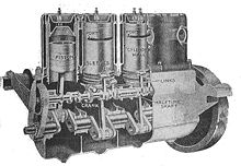
A 4-cylinder car engine of 1919, sectioned through the cylinders to show the Knight sleeve valves.
Knight sleeve-valve engine

The first successful sleeve valve was patented by Charles Yale Knight, and used twin alternating sliding sleeves. It was used in some luxury automobiles, notably Willys, Daimler, Mercedes-Benz, Minerva, Panhard, Peugeot and Avions Voisin. Mors adopted double sleeve-valve engines made by Minerva.The higher oil consumption was heavily outweighed by the quietness of running and the very high mileages without servicing. Early poppet-valve systems required decarbonization at very low mileages.
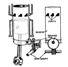
Diagram of the Argyll single sleeve valve, showing the complex shape of the multiple ports and the semi-rotary actuation
Argyll single sleeve valve


The Burt-McCollum sleeve valve was named for the two inventors that applied for similar patents within a few weeks of each other, the Burt system was an open sleeve type, driven from the crankshaft side, while the McCollum design had a sleeve in the head and upper part of the cylinder, and a more complex port arrangement (Source: 'Torque Meter' Magazine, AEHS). The design that entered production was more 'Burt' than 'McCollum,' and was used by the Scottish company Argyll for its cars, and later was adopted by Bristol for its radial aircraft engines, used a single sleeve which rotated around a timing axle set at 90 degrees to the cylinder axis. Mechanically simpler and more rugged, the Burt-McCollum valve had the additional advantage of reducing oil consumption (compared to other sleeve valve designs), while retaining the combustion chambers and big, uncluttered, porting area possible in the Knight system.

A small number of designs used a "cuff" sleeve in the cylinder head instead of the cylinder proper, providing a more "classic" layout compared to traditional poppet valve engines. This design also had the advantage of not having the piston within the sleeve, although in practice this appears to have had little practical value. On the downside, this arrangement limited the size of the ports to that of the cylinder head, whereas in-cylinder sleeves could have much larger ports.

Advantages/disadvantages.

Advantages:~

  • High volumetric efficiency due to very large port openings. Sir Harry Ricardo also demonstrated better mechanical and thermal efficiency.
  • The size of the ports can be readily controlled. This is important when an engine operates over a wide RPM range, since the speed at which air can enter and exit the cylinder is defined by the size of the duct leading to the cylinder, and varies according to the cube of the RPM. In other words, at higher RPM the engine typically requires larger ports that remain open for a greater proportion of the cycle, which is fairly easy to achieve with sleeve valves, but difficult in a poppet valve system.
  • Good exhaust scavenging and controllable swirl of the inlet air/fuel mixture in single-sleeve designs. When the intake ports open, the air/fuel mixture can be made to enter tangentially to the cylinder. This helps scavenging when exhaust/inlet timing overlap is used and a wide speed range required, whereas poor poppet valve exhaust scavenging can dilute the fresh air/fuel mixture intake to a greater degree, being more speed dependent (relying principally on exhaust/inlet system resonant tuning to separate the two streams). Greater freedom of combustion chamber design (few constraints other than the spark plug positioning) means that fuel/air mixture swirl at top dead centre (TDC) can also be more controlled allowing improved ignition and flame travel which, as demonstrated by H Ricardo, allows at least one extra unit of compression ratio before detonation, compared with the poppet valve engine.
  • The combustion chamber formed with the sleeve at the top of its stroke is ideal for complete, detonation-free, combustion of the charge, as it does not have to contend with compromised chamber shape and hot exhaust (poppet) valves.
  • No springs are involved in the sleeve valve system, therefore the power needed to operate the valve remains largely constant with the engine's RPM, meaning that the system can be used at very high speeds with no penalty for doing so. A problem with high-speed engines that use poppet valves is that as engine speed increases, the speed at which the valve moves also has to increase. This in turn increases the loads involved due to the inertia of the valve, which has to be opened quickly, brought to a stop, then reversed in direction and closed and brought to a stop again. Large poppet valves that allow good air-flow have considerable mass and require a strong spring to overcome their inertia when closing. At higher engine speeds, the valve spring may be unable to close the valve before the next opening event, resulting in a failure to completely close. This effect, called valve float can result in the valve being struck by the top of the rising piston. In addition, camshafts, push-rods, and valve rockers can be eliminated in a sleeve valve design, as the sleeve valves are generally driven by a single gear powered from the crankshaft. In an aircraft engine, this provided desirable reductions in weight and complexity.
  • Longevity, as demonstrated in early automotive applications of the Knight engine. Prior to the advent of leaded gasolines, poppet-valve engines typically required grinding of the valves and valve seats after 20,000 to 30,000 miles (32,000 to 48,000 km) of service. Sleeve valves did not suffer from the wear and recession caused by the repetitive impact of the poppet valve against its seat. Sleeve valves were also subjected to less intense heat build-up than poppet valves, owing to their greater area of contact with other metal surfaces. In the Knight engine, carbon build-up actually helped to improve the sealing of the sleeves, the engines said to "improve with use", in contrast to poppet valve engines, which lose compression and power as valves, valve stems and guides wear. Due to the continuous motion of the sleeve (Burt-McCollum type), the high wear points linked to poor lubrication in the TDC/BDC (bottom dead centre) of piston travel within the cylinder are suppressed, so rings and cylinders lasted much longer.
  • The cylinder head is not required to host valves, allowing the spark plug to be placed in the best possible location for efficient ignition of the combustion mixture. For very big engines, where flame propagation speed limits both size and speed, the swirl induced by ports, as described by Harry Ricardo can be an additional advantage. In his research with two-stroke single sleeve valve compression ignition engines, Harry Ricardo proved that an open sleeve was feasible, acting as a second annular piston with 10% of the central piston area, that transmitted 3% of the power to the output shaft through the sleeve driving mechanism. This highly simplifies construction, as the 'junk head' is no longer needed.
  • Lower operating temperatures of all power-connected engine parts, cylinder and pistons, Harry Ricardo showed that as long as the clearance between sleeve and cylinder is adequately settled, and the lubricating oil film is thin enough, sleeves are 'transparent to heat'.
  • Continental in the United States conducted extensive research in single sleeve valve engines, pointing that they were eventually of lower production cost, and easier to produce. However, their aircraft engines soon equalled the single sleeve valve engines' performance by introducing improvements such as sodium-cooled poppet valves, and it seems also that the costs of this research, along with the October 1929 crisis, led to the Continental single-sleeve-valve engines not entering mass production. A book (Continental! Its motors and its people. W Wagner, 1983. ISBN 0-8168-4506-9) on Continental Engines reports that General Motors had conducted tests with single sleeve valve engines, rejecting this kind of arrangement, and, according to M Hewland (Car&Driver, July 1974) also Ford around 1959.
Most of these advantages were evaluated and established during the 1920s by Roy Fedden and Harry Ricardo, possibly the sleeve valve engine's greatest advocate. He conceded that some of these advantages were significantly eroded as fuels improved up to and during World War II and as sodium-cooled exhaust valves were introduced in high output aircraft engines.

Disadvantages.

A number of disadvantages plagued the single sleeve valve:
  • Perfect, even very good, sealing is difficult to achieve. In a poppet valve engine, the piston possesses piston rings (at least three and sometimes as many as eight) which form a seal with the cylinder bore. During the "breaking in" period (known as "running-in" in the UK) any imperfections in one are scraped into the other, resulting in a good fit. This type of "breaking in" is not possible on a sleeve-valve engine, however, because the piston and sleeve move in different directions and in some systems even rotate in relation to one another. Mike Hewland claimed the run-in for rings in his SSV designs was 10 hrs. Unlike a traditional design, the imperfections in the piston do not always line up with the same point on the sleeve. In the 1940s this was not a major concern because the poppet valve stems of the time typically leaked appreciably more than they do today, so that oil consumption was significant in either case. To one of the 1922–1928 Argyll single sleeve valve engines, the 12, a four-cylinder 91 cu in (1,491 cc) unit, was attributed an oil consumption of one gallon for 1,945 miles, and 1,000 miles per gallon of oil in the 15/30 4 cylinder 159 cu in (2,610 cc). Mike Hewland claimed in 1974 that the progress in lubricating oils, materials, and machining had solved the oil thirst problem, his experimental 500 cc Single Cylinder engines using less oil than its contemporary poppet valve 'competitors', some proposed an added ring in the base of Sleeve, between Sleeve and cylinder wall. Single-Sleeve-Valve engines had a reputation of being much less smoky than the Daimler with engines of Knight double-sleeve engines counterparts.
  • The high oil consumption problem associated with the Knight double sleeve valve was fixed with the Burt-McCollum Single Sleeve Valve, as perfected by Bristol. The models that had the complex: 'junk head', installed on it a non-return purging valve; as liquids can't be compressed, the presence of oil in the head space would result in problems. Mike Hewland, after adding an expander ring that worked in reserve, found the oil use of his single sleeve valve engines was half of a similar poppet valve. 'In this engine all we really have to lubricate is the crankshaft, the rest seems to lubricate itself' (C&D, Jul 1974). At top dead centre (TDC), the single-sleeve valve rotates in relation to the piston. This prevents boundary lubrication problems, as piston ring ridge wear at TDC and bottom dead centre (BDC) does not occur. The Bristol Hercules TBO overhaul life was rated at 3,000 hours, very good for an aircraft engine, but not so for automotive engines. Sleeve wear was located primarily in the upper part, inside the: 'Junk Head'.
  • An inherent disadvantage is that the piston in its course partially obscures the ports, thus making it difficult for gases to flow during the crucial overlap between the intake and exhaust valve timing usual in modern engines. Mike Hewland admitted this was a problem at speeds above 10,000 rpm in his engines aimed at racing, but in the middle range, S S-V was always better than a poppet valve engine. The 1954 printing of the book by Harry Ricardo: 'The high-speed internal combustion engine', and also some patents on sleeve valve production, point out that the available zone for ports in the sleeve depends on the type of sleeve drive and bore/stroke ratio; Ricardo tested successfully the: 'Open Sleeve' concept in some two-stroke, compression ignition engines, it not only eliminated the head rings, but allowed a reduction in height of the engine and head, thus frontal area in an aircraft engine, the whole circumference of the sleeve being available for exhaust port area, and the sleeve acting in phase with the piston forming an annular piston with an area around 10% of that of the piston, that contributed to some 3% of power output through the sleeve driving mechanism to the crankshaft. The German born engineer Max Bentele, after studying a British sleeve valve aero engine (probably a Hercules), complained that the arrangement required more than 100 gearwheels for the engine, too many for his taste.
  • A serious issue with large Single-Sleeve aero-engines is that their maximum reliable rotational speed is limited to about 3000 RPM, but the M Hewland car engine was raced above 10'000 rpm without toil.
  • Improved fuel octanes, above about 87 RON, have assisted poppet-valve engines’ power output more than to the Single-Sleeve engines’.
  • The increased difficulty with oil consumption and cylinder-assembly lubrication was reported as never having been solved in series-produced engines, ChargerMiles007, from a Canadian University, proposed adding a ring in the lower outer part of sleeve to reduce oil consumption, Railroad and other big size Single Sleeve-Valve engines emit more smoke upon start, and as the engine reaches operating temperature, and tolerances enter the adequate range, smoke is greatly reduced. For 2-Stroke egnines, a three way catalyst, with air injection in the middle, was proposed as best solution in a SAE Journal article around year 2000.
  • Some (Wifredo Ricart, Alfa-Romeo) feared the build-up of heat inside the cylinder, however Ricardo proved that if only a thin oil film is retained and working clearance between the sleeve and the cylinder barrel was kept small, moving sleeves are almost transparent to heat, actually transporting heat from upper to lower parts of the system.
  • If stored horizontally, sleeves tend to become oval, producing several types of mechanical problems. To avoid this, special cabinets were developed to store sleeves vertically.
  • Equivalent implementations of modern variable valve timing and variable lift are impossible due to the fixed sizes of the port holes and essentially fixed rotational speed of the sleeves. It may theoretically be possible to alter the rotational speed through gearing that is not linearly related to the engine speed, however it seems this would be impractically complex even compared to the complexities of modern valve control systems.

History.

Charles Yale Knight:~

Daimler 22 hp open 2-seater (1909 example). The clearly visible mascot on its radiator cap is (C. Y.'s) Knight


In 1901 Knight bought an air-cooled, single-cylinder three-wheeler whose noisy valves annoyed him. He believed that he could design a better engine and did so, inventing his double sleeve principle in 1904. Backed by Chicago entrepreneur L.B. Kilbourne, a number of engines were constructed followed by the "Silent Knight" touring car which was shown at the 1906 Chicago Auto Show.

Knight's design had two cast-iron sleeves per cylinder, one sliding inside the other with the piston inside the inner sleeve. The sleeves were operated by small connected rods actuated by an eccentric shaft. They had ports cut out at their upper ends. The design was remarkably quiet, and the sleeve valves needed little attention. It was, however, more expensive to manufacture due to the precision grinding required on the sleeves' surfaces. It also used more oil at high speeds and was harder to start in cold weather.

A replicated 1912 Stearns advertisement in downtown Boise, Idaho touting the Knight-type motor

Although he was initially unable to sell his Knight Engine in the United States, a long sojourn in England, involving extensive further development and refinement by Daimler supervised by their consultant Dr Frederick Lanchester eventually secured Daimler and several luxury car firms as customers willing to pay his expensive premiums. He first patented the design in England in 1908. The patent for the US was granted 1910. As part of the licensing agreement, "Knight" was to be included in the car's name.

Six cylinder Daimler sleeve valve engines were used in the first British tanks in WW1, up to and including the Mark IV. As a result of the tendency of the engines to smoke and hence give away the tank positions, Harry Ricardo was brought in, and devised a new engine which replaced the sleeve valve starting with the Mark V tank.

Among the companies using Knight's technology were Avions Voisin, Daimler (1909–1930s) including their V12 Double Six, Panhard (1911–39), Mercedes (1909–24), Willys (as the Willys-Knight, plus the associated Falcon-Knight), Stearns, Mors, Peugeot, and Belgium's Minerva company that was forced to stop their sleeve-valve line of engines as a result of the limitations imposed on them by the winners of WWII, some thirty companies in all. Itala also experimented with rotary and sleeve valves in their 'Avalve' cars.

Upon Knight's return to America he was able to get some firms to use his design; here his brand name was "Silent Knight" (1905–1907) — the selling point was that his engines were quieter than those with standard poppet valves. The best known of these were the F.B. Stearns Company of Cleveland, which sold a car named the Stearns-Knight, and the Willys firm which offered a car called the Willys-Knight, which was produced in far greater numbers than any other sleeve-valve car.

Burt-McCollum.

The Burt-McCollum sleeve valve, having its name from the surnames of the two engineers that patented the same concept with weeks of difference, Peter Burt and James Harry Keighly McCollum, patent applications are of August 6 and June 22, 1909, respectively, both engineers hired by the Scottish car maker Argyll, consisted of a single sleeve, which was given a combination of up-and-down and partial rotary motion. It was developed in about 1909 and was first used in the 1911 Argyll car. The initial 1900 investment in Argyll was ₤15,000 and building the magnificent Scotland plant cost ₤500,000 in 1920. It is reported that litigation by the owners of the Knight patents cost Argyll ₤50,000, perhaps one of the reasons for the temporary shutdown of their plant. Another car maker that used the Argyll SSV patents was Piccard-Pictet (Pic-Pic); Louis Chevrolet and others founded Frontenac Motors in 1923 with the aim of producing an 8-L SSV engined luxury car, but this never reached production for reasons connected to the time limits to the Argyll patents in the USA. The greatest success for Single Sleeve Valves (SSV) was in Bristol's large aircraft engines, it were also used in the Napier Sabre and Rolls-Royce Eagle engines. The SSV system also reduced the high oil consumption associated with the Knight double sleeve valve.

Barr and Stroud Ltd of Anniesland, Glasgow, also licensed the SSV design, and made small versions of the engines that they marketed to motorcycle companies. In an advertisement in Motor Cycle magazine in 1922 Barr & Stroud promoted their 350cc Sleeve Valve engine and listed Beardmore-Precision, Diamond, Edmund, and Royal Scot as motorcycle manufacturers offering it. This engine had been described in the March edition as the 'Burt' engine. Grindlay-Peerless started producing a SSV Barr & Stroud engined 999cc V-twin in 1923 and later added a 499cc single SSV as well as the 350cc. Some small SSV auxiliary boat engines and electric generators were built in the UK, prepared for burning 'paraffin' from start, or after a bit of heat-up with more complex fuels. (Petter Brotherhood, Wallace. 'The Engineer', Dec 9, 1921, pg 618)

A number of Sleeve Valve aircraft engines were developed following a seminal 1927 research paper from the RAE by Harry Ricardo. This paper outlined the advantages of the sleeve valve and suggested that poppet valve engines would not be able to offer power outputs much beyond 1500 hp (1,100 kW). Napier and Bristol began the development of Sleeve-Valve engines that would eventually result in limited production of two of the most powerful piston engines in the world: the Napier Sabre and Bristol Centaurus. The Continental Motors Company, around the years of the Great Depression, developed prototypes of Single Sleeve-Valve engines for a range of applications, from cars to trains to airplanes, and thought that production would be easier, and costs would be lower, than its counterpart poppet valve engines. Due to the financial problems of Continental, this line of engines never entered production. ('Continental! Its motors and its people', William Wagner, Armed Forces Journal International and Aero Publishers, 1983, ISBN 0-8168-4506-9)

Potentially the most powerful of all Sleeve-Valve engines (though it never reached production) was the Rolls-Royce Crecy V-12 (oddly, using a 90-degree V-angle), two-stroke, direct-injected, turbocharged (force-scavenged) aero-engine of 26.1 litres capacity. It achieved a very high specific output, and surprisingly good specific fuel consumption (SFC). In 1945 the single-cylinder test-engine (Ricardo E65) produced the equivalent of 5,000 HP (192 BHP/Litre) when water injected, although the full V12 would probably have been initially type rated at circa 2,500 hp (1,900 kW). Sir Harry Ricardo, who specified the layout and design goals, felt that a reliable 4,000 HP military rating would be possible. Ricardo was constantly frustrated during the war with Rolls-Royce's (RR) efforts. Hives & RR were very much focused on their Merlin, Griffon then Eagle and finally Whittle's jets, which all had a clearly defined production purpose. Ricardo and Tizard eventually realized that the Crecy would never get the development attention it deserved unless it was specified for installation in a particular aircraft but by 1945, their "Spitfire on steroids" concept of a rapidly climbing interceptor powered by the lightweight Crecy engine had become an aircraft without a purpose.

Following World War II, the sleeve valve became utilised less, Roy Fedden, very early involved in the S-V research, built some flat-six Single Sleeve-Valve engines intended for general aviation around 1947; after this, just the French SNECMA produced some SSV engines under Bristol license that were installed in the Noratlas transport airplane, also another transport aircraft, the Azor built by the Spanish CASA installed SSV Bristol engines post-WWII. Bristol sleeve valve engines were used however during the post-war air transport boom, in the Vickers Viking and related military Varsity and Valetta, Airspeed Ambassador, used on BEA's European routes, and Handley Page Hermes (and related military Hastings), and Short Solent airliners and the Bristol Freighter and Superfreighter. The Centaurus was also used in the military Hawker Sea Fury, Blackburn Firebrand, Bristol Brigand and the Fairey Spearfish. The poppet valve's previous problems with sealing and wear had been remedied by the use of better materials and the inertia problems with the use of large valves were reduced by using several smaller valves instead, giving increased flow area and reduced mass, and the exhaust valve hot spot by Sodium-cooled valves. Up to that point, the single sleeve valve had won every contest against the poppet valve in comparison of power to displacement. The difficulty of nitride hardening, then finish-grinding the sleeve valve for truing the circularity, may have been a factor in its lack of commercial application.

The Knight-Argyll Patent Case.

When the Argyll car was launched in 1911, the Knight and Kilbourne Company immediately brought a case against Argyll for infringement of their original 1905 patent. This patent described an engine with a single moving sleeve, whereas the Daimler engines being built at the time were based on the 1908 Knight patent which had engines with two moving sleeves. As part of the litigation an engine was built according to the 1905 specification and developed no more than a fraction of the rated RAC horsepower. This fact coupled with other legal and technical arguments led the judge to rule, at the end of July 1912, that the holders of the original Knight patent could not be supported in their claim that it gave them master rights encompassing the Argyll design.

Modern usage.

The sleeve valve has begun to make something of a comeback, due to modern materials, dramatically better engineering tolerances and modern construction techniques, which produce a sleeve valve that leaks very little oil. However, most advanced engine research is concentrated on improving other internal combustion engine designs, such as the Wankel.

Mike Hewland with his assistant John Logan, and also independently Keith Duckworth, experimented with a single-cylinder sleeve-valve test engine when looking at Cosworth DFV replacements. Hewland claimed to have obtained 72 hp (54 kW) from a 500 cc single-cylinder engine, with a specific fuel consumption of 177-205 gr/HP/hr (0.39 - 0.45 lb/HP/hr), the engine being able to work on creosote, and with no specific lubrication supply for the sleeve.

An unusual form of four-stroke model engine that uses what is essentially a sleeve-valve format, is the British RCV series of "SP" model engines, which use a rotating cylinder liner driven through a bevel gear at the cylinder liner's "bottom" and, even more unusually, have the propeller shaft — as an integrally machined part of the rotating cylinder liner — emerging from what would normally be the cylinder's "top" at the extreme front of the engine, achieving a 2:1 gear reduction ratio compared to the vertically oriented crankshaft's rotational speed. The same firm's "CD" series of model engines use a conventional upright single cylinder with the crankshaft used to spin the propeller directly and also use the rotating cylinder valve. As a parallel with the earlier Charles Knight-designed sleeve-valved automotive powerplants, any RCV sleeve-valved model engine that is run on model glow engine fuel using castor oil (about 2% to 4% content) of the lubricant in the fuel allows the "varnish" created through engine operation to provide a better pneumatic seal between the rotating cylinder valve and the unitized engine cylinder/head castings, initially formed while the engine is being broken in.

Sunday, 23 October 2016

Crankshaft

Crankshaft:~


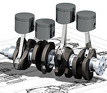
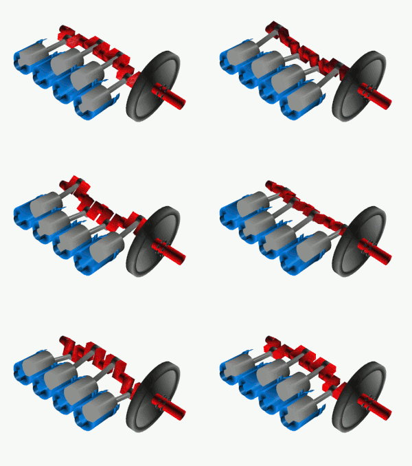
Flat-plane crankshaft (red), pistons (gray) in their cylinders (blue), and flywheel (black)

A crankshaft—related to crank—is a mechanical part able to perform a conversion between reciprocating motion and rotational motion. In a reciprocating engine, it translates reciprocating motion of the piston into rotational motion; whereas in a reciprocating compressor, it converts the rotational motion into reciprocating motion. In order to do the conversion between two motions, the crankshaft has "crank throws" or "crankpins", additional bearing surfaces whose axis is offset from that of the crank, to which the "big ends" of the connecting rods from each cylinder attach.

It is typically connected to a flywheel to reduce the pulsation characteristic of the four-stroke cycle, and sometimes a torsional or vibrational damper at the opposite end, to reduce the torsional vibrations often caused along the length of the crankshaft by the cylinders farthest from the output end acting on the torsional elasticity of the metal.

History:~

Roman Empire

Roman crank dated to the 2nd century AD. The right handle is lost.

A Roman iron crank of yet unknown purpose dating to the 2nd century AD was excavated in Augusta Raurica, Switzerland. The 82.5 cm long piece has fitted to one end a 15 cm long bronze handle, the other handle being lost.

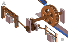
Roman Hierapolis sawmill from the 3rd century AD, the earliest known machine to combine a crank with a connecting rod.

The earliest evidence, anywhere in the world, for a crank and connecting rod in a machine appears in the late Roman Hierapolis sawmill from the 3rd century AD and two Roman stone sawmills at Gerasa, Roman Syria, and Ephesus, Asia Minor (both 6th century AD). On the pediment of the Hierapolis mill, a waterwheel fed by a mill race is shown transmitting power through a gear train to two frame saws, which cut rectangular blocks by way of some kind of connecting rods and, through mechanical necessity, cranks. The accompanying inscription is in Greek.

The crank and connecting rod mechanisms of the other two archaeologically attested sawmills worked without a gear train. In ancient literature, we find a reference to the workings of water-powered marble saws close to Trier, now Germany, by the late 4th century poet Ausonius; about the same time, these mill types seem also to be indicated by the Christian saint Gregory of Nyssa from Anatolia, demonstrating a diversified use of water-power in many parts of the Roman Empire. The three finds push back the date of the invention of the crank and connecting rod back by a full millennium; for the first time, all essential components of the much later steam engine were assembled by one technological culture:
With the crank and connecting rod system, all elements for constructing a steam engine (invented in 1712) — Hero's aeolipile (generating steam power), the cylinder and piston (in metal force pumps), non-return valves (in water pumps), gearing (in water mills and clocks) — were known in Roman times.

Medieval East

Al-Jazari (1136–1206) described a crank and connecting rod system in a rotating machine in two of his water-raising machines. His twin-cylinder pump incorporated a crankshaft, though the device was unnecessarily complex.

In China, the potential of the crank of converting circular motion into reciprocal one never seems to have been fully realized, and the crank was typically absent from such machines until the turn of the 20th century.

Medieval Europe

Vigevano's war carriage

The Italian physician Guido da Vigevano (c. 1280−1349), planning for a new crusade, made illustrations for a paddle boat and war carriages that were propelled by manually turned compound cranks and gear wheels (center of image). The Luttrell Psalter, dating to around 1340, describes a grindstone rotated by two cranks, one at each end of its axle; the geared hand-mill, operated either with one or two cranks, appeared later in the 15th century;


Renaissance Europe

15th century paddle-wheel boat whose paddles are turned by single-throw crankshafts (Anonymous of the Hussite Wars)

The first depictions of the compound crank in the carpenter's brace appear between 1420 and 1430 in various northern European artwork. The rapid adoption of the compound crank can be traced in the works of the Anonymous of the Hussite Wars, an unknown German engineer writing on the state of the military technology of his day: first, the connecting-rod, applied to cranks, reappeared, second, double compound cranks also began to be equipped with connecting-rods and third, the flywheel was employed for these cranks to get them over the 'dead-spot'.

In Renaissance Italy, the earliest evidence of a compound crank and connecting-rod is found in the sketch books of Taccola, but the device is still mechanically misunderstood. A sound grasp of the crank motion involved is demonstrated a little later by Pisanello, who painted a piston-pump driven by a water-wheel and operated by two simple cranks and two connecting-rods.

Water-raising pump powered by crank and connecting rod mechanism (Georg Andreas Böckler, 1661)

One of the drawings of the Anonymous of the Hussite Wars shows a boat with a pair of paddle-wheels at each end turned by men operating compound cranks (see above). The concept was much improved by the Italian Roberto Valturio in 1463, who devised a boat with five sets, where the parallel cranks are all joined to a single power source by one connecting-rod, an idea also taken up by his compatriot Francesco di Giorgio.

Crankshafts were also described by Konrad Kyeser (d. 1405), Leonardo da Vinci (1452–1519) and a Dutch "farmer" by the name Cornelis Corneliszoon van Uitgeest in 1592. His wind-powered sawmill used a crankshaft to convert a windmill's circular motion into a back-and-forward motion powering the saw. Corneliszoon was granted a patent for his crankshaft in 1597.

From the 16th century onwards, evidence of cranks and connecting rods integrated into machine design becomes abundant in the technological treatises of the period: Agostino Ramelli's The Diverse and Artifactitious Machines of 1588 alone depicts eighteen examples, a number that rises in the Theatrum Machinarum Novum by Georg Andreas Böckler to 45 different machines, one third of the total.

Internal combustion engines

Water-raising pump powered by crank and connecting rod mechanism (Georg Andreas Böckler, 1661)

MAN marine crankshaft for 6cyl marine diesel applications. Note locomotive on left for size reference

Large engines are usually multicylinder to reduce pulsations from individual firing strokes, with more than one piston attached to a complex crankshaft. Many small engines, such as those found in mopeds or garden machinery, are single cylinder and use only a single piston, simplifying crankshaft design.

A crankshaft is subjected to enormous stresses, potentially equivalent of several tonnes of force. The crankshaft is connected to the fly-wheel (used to smooth out shock and convert energy to torque), the engine block, using bearings on the main journals, and to the pistons via their respective con-rods. An engine loses up to 75% of its generated energy in the form of friction, noise and vibration in the crankcase and piston area. The remaining losses occur in the valvetrain (timing chains, belts, pulleys, camshafts, lobes, valves, seals etc.) heat and blow by.

Bearings

The crankshaft has a linear axis about which it rotates, typically with several bearing journals riding on replaceable bearings (the main bearings) held in the engine block. As the crankshaft undergoes a great deal of sideways load from each cylinder in a multicylinder engine, it must be supported by several such bearings, not just one at each end. This was a factor in the rise of V8 engines, with their shorter crankshafts, in preference to straight-8 engines. The long crankshafts of the latter suffered from an unacceptable amount of flex when engine designers began using higher compression ratios and higher rotational speeds. High performance engines often have more main bearings than their lower performance cousins for this reason.

Piston stroke

The distance the axis of the crank throws from the axis of the crankshaft determines the piston stroke measurement, and thus engine displacement. A common way to increase the low-speed torque of an engine is to increase the stroke, sometimes known as "shaft-stroking." This also increases the reciprocating vibration, however, limiting the high speed capability of the engine. In compensation, it improves the low speed operation of the engine, as the longer intake stroke through smaller valve(s) results in greater turbulence and mixing of the intake charge. Most modern high speed production engines are classified as "over square" or short-stroke, wherein the stroke is less than the diameter of the cylinder bore. As such, finding the proper balance between shaft-stroking speed and length leads to better results.

Engine configuration

The configuration, meaning the number of pistons and their placement in relation to each other leads to straight, V or flat engines. The same basic engine block can sometimes be used with different crankshafts, however, to alter the firing order. For instance, the 90° V6 engine configuration, in older days sometimes derived by using six cylinders of a V8 engine with a 3 throw crankshaft, produces an engine with an inherent pulsation in the power flow due to the "gap" between the firing pulses alternates between short and long pauses because the 90 degree engine block does not correspond to the 120 degree spacing of the crankshaft. The same engine, however, can be made to provide evenly spaced power pulses by using a crankshaft with an individual crank throw for each cylinder, spaced so that the pistons are actually phased 120° apart, as in the GM 3800 engine. While most production V8 engines use four crank throws spaced 90° apart, high-performance V8 engines often use a "flat" crankshaft with throws spaced 180° apart, essentially resulting in two straight four engines running on a common crankcase. The difference can be heard as the flat-plane crankshafts result in the engine having a smoother, higher-pitched sound than cross-plane (for example, IRL IndyCar Series compared to NASCAR Sprint Cup Series, or a Ferrari 355 compared to a Chevrolet Corvette). This type of crankshaft was also used on early types of V8 engines. See the main article on crossplane crankshafts.

Engine balance

For some engines it is necessary to provide counterweights for the reciprocating mass of each piston and connecting rod to improve engine balance. These are typically cast as part of the crankshaft but, occasionally, are bolt-on pieces. While counter weights add a considerable amount of weight to the crankshaft, it provides a smoother running engine and allows higher RPM levels to be reached.

Flying arms

Crankshaft with flying arms (the boomerang-shaped link between the visible crankpins)

In some engine configurations, the crankshaft contains direct links between adjacent crankpins, without the usual intermediate main bearing. These links are called flying arms. This arrangement is sometimes used in V6 and V8 engines as it enables the engine to be designed with different V angles than what would otherwise be required to create an even firing interval, while still using fewer main bearings than would normally be required with a single piston per crankthrow. This arrangement reduces weight and engine length at the expense of less crankshaft rigidity.

Rotary aircraft engines

Some early aircraft engines were a rotary engine design, where the crankshaft was fixed to the airframe and instead the cylinders rotated with the propeller.

Radial engines

The radial engine is a reciprocating type internal combustion engine configuration in which the cylinders point outward from a central crankshaft like the spokes of a wheel. It resembles a stylized star when viewed from the front, and is called a "star engine" (German Sternmotor, French Moteur en étoile) in some languages. The radial configuration was very commonly used in aircraft engines before turbine engines became predominant.

Construction:~

Continental engine marine crankshafts, 1942

Crankshafts can be monolithic (made in a single piece) or assembled from several pieces. Monolithic crankshafts are most common, but some smaller and larger engines use assembled crankshafts.

Forging and casting

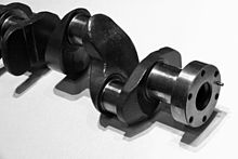
Forged crankshaft

Crankshafts can be forged from a steel bar usually through roll forging or cast in ductile steel. Today more and more manufacturers tend to favor the use of forged crankshafts due to their lighter weight, more compact dimensions and better inherent damping. With forged crankshafts, vanadium microalloyed steels are mostly used as these steels can be air cooled after reaching high strengths without additional heat treatment, with exception to the surface hardening of the bearing surfaces. The low alloy content also makes the material cheaper than high alloy steels. Carbon steels are also used, but these require additional heat treatment to reach the desired properties. Iron crankshafts are today mostly found in cheaper production engines (such as those found in the Ford Focus diesel engines) where the loads are lower. Some engines also use cast iron crankshafts for low output versions while the more expensive high output version use forged steel.

Machining

Crankshafts can also be machined out of a billet, often a bar of high quality vacuum remelted steel. Though the fiber flow (local inhomogeneities of the material's chemical composition generated during casting) doesn’t follow the shape of the crankshaft (which is undesirable), this is usually not a problem since higher quality steels, which normally are difficult to forge, can be used. These crankshafts tend to be very expensive due to the large amount of material that must be removed with lathes and milling machines, the high material cost, and the additional heat treatment required. However, since no expensive tooling is needed, this production method allows small production runs without high costs.

In an effort to reduce costs, used crankshafts may also be machined. A good core may often be easily reconditioned by a crankshaft grinding  process. Severely damaged crankshafts may also be repaired with a welding operation, prior to grinding, that utilizes a submerged arc welding machine. To accommodate the smaller journal diameters a ground crankshaft has, and possibly an over-sized thrust dimension, undersize engine bearings are used to allow for precise clearances during operation.

Machining or remanufacturing crankshafts are precision machined to exact tolerances with no odd size crankshaft bearings or journals. Thrust surfaces are micro-polished to provide precise surface finishes for smooth engine operation and reduced thrust bearing wear. Every journal is inspected and measured with critical accuracy. After machining, oil holes are chamfered to improve lubrication and every journal polished to a smooth finish for long bearing life. Remanufactured crankshafts are thoroughly cleaned with special emphasis to flushing and brushing out oil passages to remove any contaminants. Typically there are 23 steps to re-manufacturing a crankshaft which are as follows:

Step 1: Industrial cleaning

The first step in the industrial crankshaft remanufacturing process is cleaning the entire crankshaft. Machine shops soak the rebuilt crankshafts in a hot tank and use a power washing station on the overall shaft as needed. Next machinists then wire brush all oil holes to remove caked on residue and other substances.

Step 2: Magnetic particle inspection

The second step in the crankshaft remanufacturing process is using a magnetic particle inspection method to check for cracks. The crankshaft is maganitized and sprayed with a iron oxide powder which, under blacklight conditions, makes any cracks or imperfections visible. All remanufactured crankshafts are checked for imperfections before proceeding forward in the manufacturing process.

Step 3: Check counterweights

The machine shop then removes and cleans the counterweights. The production facility then checks the counterweights to make sure they are tight. If the counterweights are loose a technician then replaces all of the counterweight bolts. Counterweights are inspected for cracks before being replaced or retightened. In step sixteen the machinist re-installs the counterweights back into the rebuilt crankshafts.

Step 4: Check crankshaft bearings and straightness

The machinist then inspects the entire incoming remanufactured crankshaft for damage and determines the size of the journals and mains. Next the machinist checks the hardness of the mains and journals. It is crucial to also inspect the crankshaft bearings and check the straightness of the overall crankshaft. Re-straightening the industrial crankshaft if not up to OEM standards occurs in step seven. Veteran machine shops typically do not re-straighten the rebuilt crankshafts until a quality control technician checks the bolt holes and seals the surface for divots.

Step 5: Check bolt holes

The technician checks the keyway, nose, bolt holes and seals the surface for non-conformities. Usually machine shops will tap bolt holes up to but not more than ½” on all remanufactured crankshafts.

Step 6: Stamp counterweight webbing

The rebuild team next stamps the counterweights & webbing in proper firing order (alpha if numeric & vice versa). Technicians then stamp the employee ID#, Work Order # and date on #1 rod webbing. Stamping this information on the rod webbing helps keep the quality control process order in case of future issues during the manufacturing process.

Step 7: Re-straightening for rebuilt crankshafts

The seventh step is industrial crankshaft re-straightening. If the remanufactured crankshaft is deemed un-straight than technicians use an industrial straightening machine on the crankshaft. The straightening machine determines how many dials are out of line. To re-straighten the shaft technicians heat up the crankshaft to 500-600 degrees. Any more than 700 degrees takes the hardness out of the shaft. The strightener process corrects the bent crankshaft to the proper OEM specifications for rebuilt crankshafts.

Step 8: Repeat magnetic particle inspection process

The eight step in the process is repeating the magnetic particle inspection process if straightening was performed. Anytime metal is being stressed it is imperative to re-inspect for cracks and structural imperfections on the reman crankshaft.

Step 9: Undercutting

The ninth step in the industrial crankshaft re-manufacturing process is undercutting. Technicians undercut the rod or journals to eliminate wear before buildup.

Step 10: Thermal spraying

The tenth step is the prevention of further buildup via metalizing often called thermal spraying. Thermal spraying has been around for well over 100 years but is still widely known as the best preventative corrosion fighting technique in the world. Thermal spraying is also known for changing the surface of the metallic component and is common with rebuilt crankshafts. Thermal spraying involves protrusion of molten particles onto the heated metallic surface where is bonds and forms a smooth coating interwoven into the structure. There are many different types of thermal spray alloys that can be employed for re-manufactured crankshafts. Typically, boron alloys are used as they very dense, hard and are oxide free. They also prevent against abrasive materials that cause divots, scratches and cracks in addition to preventing surface erosion and corrosion. Thermal spray is an important step some machine shops employ, but not always performed in the industry.

Step 11: Industrial crankshaft welding

The welding process for re-manufactured crankshafts is called submerged arc welding. It is a powdered flux plus a weld which combines to produce a more precise weld. The most common flux powder used is called #1 Flux 2245 HD. This powder eliminates the need for technicians to wear weld masking and reduces the amount of dust by-product.

Step 12: Relieve structural stress

The twelfth step is to relieve stress upon the entire rebuilt crankshaft structure by heating it up again to 500-600 degrees.

Step 13: Recheck for straightness

Next step is to check for overall straightness of the re-manufactured crankshaft once again. If the re-manufactured crankshaft is out of alignment then the technician repeats step 7 and re-straighten the structure. Each of the re-manufactured crankshafts is checked multiple times throughout the re-manufacturing process to ensure quality control. If the straightness is not compromised the rebuilt crankshafts can proceed to step thirteen which is crankshaft grinding.

Step 14: Rough crankshaft grinding

This is one of the most important steps in the re-manufacturing process of industrial crankshafts. This step involves rough grinding the excess material from the rod or journals and is known as crankshaft grinding. On the rod there are various mains that need to be reground to proper OEM specifications. These rods are spun grind to the next under-size using the pultrusion crankshaft grinding machine. Rod mains are ground inside and outside. Machine shops have the ability to “crankshaft grind” to any size to bring back the crankshaft to standard OEM specifications.

Step 15: Finished crankshaft grinding

Next the technician performs a finished crankshaft grinding procedure. The finished crankshaft grinding is a more precise grind which reaches the correct OEM specifications. Before the technician starts the crankshaft grinding they should see what crankshaft bearings are available and start from there. For example, the OEM specification for a Caterpillar 3306 Rod is 2.9987” – 3.0003”. Top industrial crankshaft grinding technicians always stop at the high end of the tolerance level. Lastly the technician further refines the crankshaft grinding process in during the micro-polishing process at step eighteen.

Step 16: Shot peening

The next step is to process the industrial crankshaft in using shot peen machinery. Shot peening adds an additional layer of hardness to the re-manufactured crankshaft.

Step 17: Replace or re-tighten counterweights

Step 17 involves replacing the counterweights in proper firing order. Either the new counterweights are installed or the old counterweight bolts are re-tightened and tested.

Step 18: Determine proper balance

The machine shop then determines if the proper rotational balance of the re-manufactured crankshafts is achieved. In the engine the crankshaft, pistons and rods all in a constant rotation. The counterweights are designed to offset the weight of the rod and the pistons in the engine. When in motion the kinetic energy and the sum of all forces should be equal to zero on all moving parts. If the re-manufactured crankshaft counterweights are imbalanced it adds additional stress on other components of the engine. The technician should then make sure the internal balance and the external balance of the crankshaft counterweights are properly aligned.

Step 19: Micro-polishing

Then the technician micro-polishes each of the rebuilt crankshafts by hand. To further refine the crankshaft grinding process the machinist makes the most precise fit by micro-polishing the component with a 600 grit emery cloth. Through micro-polishing and industrial crankshaft grinding, the machine shop achieves the recommended Rockwell hardness and Ra finish (Roughness Parameter).

Step 20: Test reman crankshaft Rockwell hardness

Next the technician checks the industry standard hardness. Industry standards crankshaft hardness is 40 on the Rockwell hardness scale. A 45-50 rating is what most reputable machine shops try to employ for all remanufactured crankshafts. When possible it is wise to go beyond industry standards to prevent any future weaknesses within the unit. Typically, hardness can be reduced if the engine is out of oil or the journal is spun incorrectly.

Step 21: Final quality control inspection

Quality control inspects all of the finished reman crankshafts for internal and external mistakes. A typical quality control department uses separate testing and analytical measurement tools from the technicians to ensure accuracy. If the rebuilt crankshaft passes the quality control inspection it goes onto the rust proofing stage.

Step 22: Rustproof remanufactured crankshaft

The vast majority of machine shops apply rust proofing to all remanufactured crankshafts using Cosmoline, which is standard rust-proofing for engine parts.

Step 23: Packaging

Lastly the machine shop packs the finished rebuilt crankshaft correctly making sure to using proper boxing and damage proof coverings. It is important to cover the rod journals (varies per crankshaft) with paper & tape in place.

Microfinishing:~

To achieve the required specifications, automotive manufacturers which design and produce high-volume, low-cost powertrain components, strive toward surpassing stringent emissions and efficiency regulations (see Euro 6c standards for reference) to reduce losses. In motorsport, powertrain developers strive to increase power output by reducing weight, using strong metal alloys, hardening crankshafts, improving balance, reducing friction and vibration as previously described.

To achieve the required specifications, automotive and motorsport powertrain designers and manufacturers adopt a process called microfinishing. Microfinishing (or superfinishing) is an engineering function concerned with metrology and tribology. Microfinishing takes place after the crankshaft grinding process, and is used to improve the geometry of the crankshaft journals from waviness, peaks and lapping caused by the grinding process and establish surface roughness as low as Ra = 0.01 µm if required.

Microfinished crankshafts show improved roundness and cylindricity for each main and pin and thrust journal, and where applicable the oil seal journal. Another important function to a geometrically correct shape is to provide it with a specific surface roughness as per design requirements for optimum lubrication hydrodynamics (essential for crankshafts in engines with stop/start fuel saving technology).

Today, crankshafts used in outboard engines, motorbikes, cars, trucks, busses, marine engines and electric generators and racing engines, are all microfinished for optimum performance. They are designed and manufactured to transfer as much energy to the fly-wheel and drivetrain and absorb as much power from the con-rods, as efficiently as possible for as long as possible.

With this new technology, a light weight, turbocharged 2.0 liter, 4 cylinder diesel engine, (with a low-cost 4 pin, 5 main induction hardened, cast steel, microfinished crankshaft), in a small family car, potentially delivers 180 hp and provides an average fuel consumption of 60 miles per gallon and beyond.

Fatigue strength:~

The fatigue strength of crankshafts is usually increased by using a radius at the ends of each main and crankpin bearing. The radius itself reduces the stress in these critical areas, but since the radius in most cases is rolled, this also leaves some compressive residual stress in the surface, which prevents cracks from forming.

Hardening:~

Most production crankshafts use induction hardened bearing surfaces, since that method gives good results with low costs. It also allows the crankshaft to be reground without re-hardening. But high performance crankshafts, billet crankshafts in particular, tend to use nitridization instead.

Nitridization is slower and thereby more costly, and in addition it puts certain demands on the alloying metals in the steel to be able to create stable nitrides. The advantage of nitridization is that it can be done at low temperatures, it produces a very hard surface, and the process leaves some compressive residual stress in the surface, which is good for fatigue properties. The low temperature during treatment is advantageous in that it doesn’t have any negative effects on the steel, such as annealing. With crankshafts that operate on roller bearings, the use of carburization tends to be favored due to the high Hertzian contact stresses in such an application. Like nitriding, carburization also leaves some compressive residual stresses in the surface.

Counterweights:~

Some expensive, high performance crankshafts also use heavy-metal counterweights to make the crankshaft more compact. The heavy-metal used is most often a tungsten alloy but depleted uranium has also been used. A cheaper option is to use lead, but compared with tungsten its density is much lower.

Stress on crankshafts:~

The shaft is subjected to various forces but generally needs to be analysed in two positions. Firstly, failure may occur at the position of maximum bending; this may be at the centre of the crank or at either end. In such a condition the failure is due to bending and the pressure in the cylinder is maximal. Second, the crank may fail due to twisting, so the conrod needs to be checked for shear at the position of maximal twisting. The pressure at this position is the maximal pressure, but only a fraction of maximal pressure.


Saturday, 22 October 2016

Design and Development of Automobile Silencer for Effective Vibration Control

Design and Development of Automobile Silencer for Effective Vibration Control.


Abstract.

 A Silencer is a part of the exhaust system of an automobile that plays a vital role. It needs to have modes that are located away from the frequencies that the engine operates at, whether the engine be idling or running at the maximum amount of revolutions per second This paper postulates the first stage in the design analysis of an exhaust system. With the specified properties of the material, the exhaust system is modeled by using a conventional FEM package. The results are compared with the reading taken on FFT analyzer, so as to distinguish working frequency fromnatural frequency and avoid resonating condition.

I. RELEVANCE.

The purpose of the exhaust system is simple: to channel the fiercely hot products of fuel combustion away from the engine or generator and the car's occupants and out into the atmosphere. The exhaust system has a secondary purpose- to reduce the amount of noise made. The exhaust gases leave the engine at incredibly high speeds. Moreover, with the opening and shutting of the exhaust valves with each cycle of combustion for each cylinder, the gas pressure alternates from high to low causing a vibration- and hence sound. Silencer has to muffle the vibrations of the exhaust gases, reduce their velocity and thus reduce the amount of noise emitted from the engines. The pulsating low from each cylinder's exhaust process of an
automobile petrol or diesel engine sets up pressure waves in the exhaust system-the exhaust port and the manifold having average pressure levels higher than the atmospheric. This varies with the engine speed and load. At higher speeds and loads the exhaust manifold is at pressures substantially above atmospheric pressure. These pressure waves propagate at speed of the sound relative to the moving exhaust gas, which escapes with a high velocity producing an objectionable exhaust boom or noise. A suitably designed exhaust silencer or Silencer accomplishes the muffling of this exhaust noise.
 

II. NEED FOR ANALYSIS.

The Automobile silencer under study belongs to a popular 2-Wheeler manufacturer in India with the rated HP of the engine upto @13.5HP. The exhaust gases coming out from engine are at very high speed and temperature. Silencer has to reduce noise, vibrations. While doing so it is subjected to thermal, vibration and fatigue failures which cause cracks. So it is necessary to analyze the vibrations which would further help to pursue future projects to minimize cracks, improving life and efficiency of silencer.

Muffler.

Muffler (silver) and exhaust pipe on a Ducati 695 motorcycle

A muffler (silencer in many non-US English speaking countries) is a device for decreasing the amount of noise emitted by the exhaust of an internal combustion engine.

History.

The US Patent for an ‘Exhaust muffler for engines’ was awarded to Milton O. Reeves and Marshall T. Reeves of Columbus, Indiana of the Reeves Pulley Company on 11 May 1897. US Patent Office application № 582485 states that they “have invented certain new and useful Improvements in Exhaust-Mufflers for engines”.

Description

Dual tailpipes attached to the muffler on a passenger car

Mufflers are installed within the exhaust system of most internal combustion engines, although the muffler is not designed to serve any primary exhaust function. The muffler is engineered as an acoustic soundproofing device designed to reduce the loudness of the sound pressure created by the engine by way of acoustic quieting. The majority of the sound pressure produced by the engine is emanated out of the vehicle using the same piping used by the silent exhaust gases absorbed by a series of passages and chambers lined with roving fiberglass insulation and/or resonating chambers harmonically tuned to cause destructive interference wherein opposite sound waves cancel each other out. An unavoidable side effect of muffler use is an increase of back pressure which decreases engine efficiency. This is because the engine exhaust must share the same complex exit pathway built inside the muffler as the sound pressure that the muffler is designed to mitigate.

A muffler on a large diesel-powered truck

Some vehicle owners remove or install an aftermarket muffler when engine tuning in order to increase power output or reduce fuel consumption because of economic or environmental concerns, recreational pursuits such as motorsport and hypermiling and/or for personal aesthetic acoustical preferences. Although the legality of altering a motor vehicle's OEM exhaust system varies by jurisdiction, in many developed parts of the world, modification of a vehicle's exhaust system is usually highly regulated if not strictly prohibited.

Trade-off between power increase and noise reduction.

When the flow of exhaust gases from the engine to the atmosphere is obstructed to any degree, back pressure arises and the engine's efficiency, and therefore power, is reduced. Performance-oriented mufflers and exhaust systems thus strive to minimize back pressure by employing numerous technologies and methods to attenuate the sound. For the majority of such systems, however, the general rule of “more power, more noise” applies. Several such exhaust systems that utilize various designs and construction methods:
  • Vector muffler - for larger diesel trucks, uses many concentric cones, or for performance automotive applications, using angled baffles to cause exhaust impulses to cancel each other out.
  • Spiral baffle muffler - for regular cars, uses a spiral-shaped baffle system
  • Aero turbine muffler - creates partial vacuums at carefully spaced out time intervals to create negative back pressure, effectively ‘sucking’ the exhaust out of the combustion cylinders

Contact Form

Name

Email *

Message *