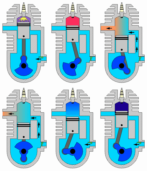
2 Stroke Engines.
 The defining characteristic of this kind of engine is that each piston completes a cycle every crankshaft revolution. The 4 processes of intake, compression, power and exhaust take place in only 2 strokes so that it is not possible to dedicate a stroke exclusively for each of them. Starting at TDC the cycle consist of:
- Power: While the piston is descending the combustion gases perform work on it—as in a 4-stroke engine—. The same thermodynamic considerations about the expansion apply.
- Scavenging: Around 75° of crankshaft rotation before BDC the exhaust valve or port opens, and blowdown occurs. Shortly thereafter the intake valve or transfer port opens. The incoming charge displaces the remaining combustion gases to the exhaust system and a part of the charge may enter the exhaust system as well. The piston reaches BDC and reverses direction. After the piston has traveled a short distance upwards into the cylinder the exhaust valve or port closes; shortly the intake valve or transfer port closes as well.
- Compression: With both intake and exhaust closed the piston continues moving upwards compressing the charge and performing a work on it. As in the case of a 4-stroke engine, ignition starts just before the piston reaches TDC and the same consideration on the thermodynamics of the compression on the charge.
{history of engines:-}
Dugald Clerk developed the first two cycle engine in 1879. It used a separate cylinder which functioned as a pump in order to transfer the fuel mixture to the cylinder.In 1899 John Day simplified Clerk's design into the type of 2 cycle engine that is very widely used today. Day cycle engines are crankcase scavenged and port timed. The crankcase and the part of the cylinder below the exhaust port is used as a pump. The operation of the Day cycle engine begins when the crankshaft is turned so that the piston moves from BDC upward (toward the head) creating a vacuum in the crankcase /cylinder area. The carburetor then feeds the fuel mixture into the crankcase through a reed valve or a rotary disk valve (driven by the engine). There are cast in ducts from the crankcase to the port in the cylinder to provide for intake and another from the exhausst port to the exhaust pipe. The height of the port in relationship to the length of the cylinder is called the "port timing."On the first upstroke of the engine there would be no fuel inducted into the cylinder as the crankcase was empty. On the downstroke the piston now compresses the fuel mix, which has lubricated the piston in the cylinder and the bearings due to the fuel mix having oil added to it. As the piston moves downward is first uncovers the exhaust, but on the first stroke there is no burnt fuel to exhaust. As the piston moves downward further, it uncovers the intake port which has a duct that runs to the crankcase. Since the fuel mix in the crankcase is under pressure the mix moves through the duct and into the cylinder.Because there is no obstruction in the cylinder of the fuel to move directly out of the exhaust port prior to the piston rising far enough to close the port, early engines used a high domed piston to slow down the flow of fuel. Later the fuel was "resonated" back into the cylinder using an expansion chamber design. When the piston rose close to TDC a spark ignites the fuel. As the piston is driven downward with power it first uncovers the exhaust port where the burned fuel is expelled under high pressure and then the intake port where the process has been completed and will keep repeating.
Later engines used a type of porting devised by the Deutz company to improve performance. It was called the Schnurle Reverse Flow system. DKW licensed this design for all their motorcycles. Their DKW RT 125 was one of the first motor vehicles to achieve over 100 mpg as a result.
 {Diesel cycle}
Main article: Diesel cycle P-v Diagram for the Ideal Diesel cycle. The cycle follows the numbers 1–4 in clockwise direction.
Most truck and automotive diesel engines use a cycle reminiscent of a four-stroke cycle, but with a compression heating ignition system, rather than needing a separate ignition system. This variation is called the diesel cycle. In the diesel cycle, diesel fuel is injected directly into the cylinder so that combustion occurs at constant pressure, as the piston moves.
Otto cycle: Otto cycle is the typical cycle for most of the cars internal combustion engines, that work using gasoline as a fuel. Otto cycle is exactly the same one that was described for the four-stroke engine. It consists of the same four major steps: Intake, compression, ignition and exhaust.PV diagram for Otto cycle On the PV-diagram, 1–2: Intake: suction stroke 2–3: Isentropic Compression stroke 3–4: Heat addition stroke 4–5: Exhaust stroke (Isentropic expansion) 5–2: Heat rejection The distance between points 1–2 is the stroke of the engine. By dividing V2/V1, we get: r, where r is called the compression ratio of the engine.


No comments:
Post a Comment